
Bently Nevada 3500 System Machinery Condition Monitoring Arr
Bently Nevada 3500 System Machinery Condition Monitoring Arrived
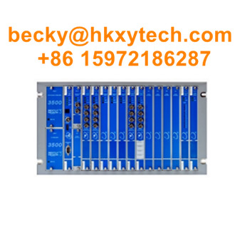
The 3500 System provides continuous,online monitoring suitable for machinery protection applications,and isdesigned to meet the requirements of the American Petroleum Institute's API 670 standard for such systemsThesystem's modula rack-based design includes the following components:
·3500/05 Instrument Rack(required)
·One or two 3500/15 Power Supplies(rcquired)
·3500/22M Transient Data Inierface(TDD)Module(required)
·One or more 3500/XX Monitor Modules(rcquired)
·One or more 3500/32M(4-chammel)or 350033(16-chamnel)Relay Modules(optional)
·One or two 350025 Keyphasor Modules*(optional)
·One or more 3500092 Commmication Gateway Modules (optional)
·Iuput/Output(CO)Modules (required)
·350094M VGA Display (opltional)
·Intermnalor cxtemal intrinsic safety bariers,or galvanic solators for hazardous area installations
System Components
This section describes the individual components that make up a complete 3500 system.
Instrument Rack
The standard 3500 Rack is available in 19” EIA rail-mount, panel-cutout-mount, and bulkhead-mount versions
Figure 1: 19” EIA Rail or Panel Mount Version
The rack provides slots for two Power Supplies and a TDI in the left-most rack positions that are reserved exclusively
for these modules. The remaining 14 slots in the rack can accommodate any combination of monitor, display, relay,
Keyphasor module, and communication gateway modules.
All modules plug into the rack’s backplane and consist of a main module and an associated I/O module. The I/O module
installs at the rear of the rack for panel-mount systems, and above the main module for bulkhead-mount systems.
Standard rack depth is 349 mm (13.75 inches), while bulkhead mount rack depth is 267 mm (10.5 inches). NEMA 4 and
4X weatherproof housings are available when required for environmental protection or when purge air is used.
Transient Data Interface (TDI)
The TDI is the 3500 Rack’s primary interface to the configuration, display, and condition monitoring
software. Each rack requires one TDI, located in the rack slot immediately adjacent to the power supply
slot.
The TDI supports a proprietary protocol used by the 3500 Configuration Software to configure the rack and
the 3500 Operator Display Software to retrieve rack data and statuses.
The TDI also provides a direct interface with System 1* Condition Monitoring and Diagnostic software
without the need for an external communications processor.
The Rack OK relay is located within the TDI’s I/O module. It is driven by NOT OK conditions within the
TDI itself and within other modules in the rack.
Dozens of possible events within the rack can drive the Rack OK relay to NOT OK condition. For
this reason, the Rack OK relay it is not intended for use as part of a machinery auto-shutdown
circuit. It should be used for general annunciation purposes only.
The TDI supports self-monitoring functions both for itself and for the rack, in addition to those provided by
the individual monitor, relay, communications, and other modules. While the TDI provides certain
functions common to the entire rack, it is not part of the critical monitoring path and its machinery
protection functions.
The TDI has four front-panel LEDs that provide the following indications:
OK Indicates that the TDI Module and its I/O Module are operating correctly.
TX/RX Flashes at the rate that communications between the TDI and other rack modules are
occurring.
TM Indicates when the rack is in the Trip Multiply mode.
CONFIG OK
Indicates that any module in the rack is not configured or has a configuration error; that the
stored configuration of the TDI does not match the physical configuration of the rack; or that a
security option condition was not met.
System configuration is secured by means of a keylock switch on the front of the TDI and two levels of
software password protection, preventing unauthorized changes to or tampering with the configuration
settings.
The TDI can be connected to a portable computer via a front-panel USB communications port for local changes to
configuration. The TDI provides permanent system connectivity via Ethernet ports. It also provides a front-panel DIP
switch for assigning a unique rack address when multiple 3500 racks are networked with one another.
The TDI has a system reset switch on the front panel for clearing any latched alarms in the system as well as latched
NOT OK conditions. The I/O module provides a set of rear-panel connections, which facilitate remote activation of the
System Reset, Trip Multiply and Rack Alarm Inhibit functions.
Each monitor occupies a single slot out of 14 available in the rack. Monitors are microprocessor-based
and offer digitally adjustable Alert and Danger setpoints for each channel. Alarms can be configured for
either latching or non-latching operation.
Status indications for each monitor are provided by front-panel LEDs, allowing observation without
operator interaction for convenient operation.
Most monitors provide independent 4 to 20 mA proportional outputs for each channel of the I/O module
for connection to associated industrial systems.
Where applicable, the I/O modules provide transducers with appropriate power via short-circuit-protected
terminals. OK detection routines within each monitor continuously check the integrity of each transducer
and associated field wiring.
Transducer input signals are buffered and sent to front-panel BNC connectors for all monitors except the
3500/60, /61, /65 (temperature) and /62 (process variable) monitors.
In addition to the direct measurement made by the monitor, many channel types provide an
enhanced data set consisting of a variety of measured variables that depend on the monitor type
and its configuration. For example, radial vibration channels include the basic overall (direct)
vibration amplitude as well as gap voltage, 1X filtered amplitude, 1X filtered phase, 2X filtered
amplitude, 2X filtered phase, Not 1X amplitude, and Smax.
These additional measured variables are provided for each channel, and ALERT alarm setpoints can be
established on each variable, as needed. DANGER alarm setpoints can be established on any
measured variable value returned from each channel.
3500 Series Monitor Modules
Monitor
Type Channel Types (footnotes)
Number of Channels
(footnotes)
3500
/40M
l Radial Vibration
l Axial (Thrust) Position
l Eccentricity
l Differential Expansion (1)
Four (2, 3)
3500
/42M
Same as 3500/40M, with the following additional channel types:
l Acceleration (4)
l Velocity (4)
l Acceleration2 (4)
l Velocity2 (4)
l Circular Acceptance Region (5)
l Shaft Absolute
Four (2, 3)
3500
/44M
l Aeroderivative
l Aeroderivative2 Four
3500
/45
l Axial (Thrust) Position
l Differential Expansion
l Standard Single Ramp Differential Expansion
l Non-Standard Single Ramp Differential Expansion
l Dual Ramp Differential Expansion
l Complementary Differential Expansion
l Case Expansion9
l Valve Position
Four (3)
3500
46M
l Hydro Radial Vibration (7)
l Hydro Stator-Mounted Air Gap
l Hydro Acceleration
l Hydro Thrust
l Hydro Velocity
l Stator End Winding
l Multimode Functionality
Four (3)
3500
/50M
l Rotor Speed
l Rotor Acceleration
l Zero-Speed
l Reverse Rotation
l Rotor Acceleration2
l Zero Speed2
l Reverse Rotation2
Two (8, 9)
3500
/60 & /61
l Temperature
l Differential Temperature Six (10)
3500
/62
l Process Variables Six (10, 11)
3500
/64M
l Dynamic Pressure Four (12)
3500
/70M
l Impulse Accel
l Acceleration2
l Recip Velocity
l Low Frequency Recip Velocity
Four
3500
/72M
l Reciprocating Compressor Rod Drop / Rod Position /
Hyper compressor
Four (3)
3500
/77M
Reciprocating Compressor Cylinder Pressure, including:
l Suction Pressure
l Maximum Pressure
l Minimum Pressure
l Compression Ratio
l Peak Rod Compression
l Peak Rod Tension
l Degree of Rod Reversal
Four3500
/82
Motor Stator Insulation Monitor
l Leakage Current (each phase)
l Line Voltage (each phase)
l Temperature (up to three channels)
Nine
Monitor Module Footnotes
1. Only standard differential expansion capabilities provided. For ramp differential expansion and complementary
input differential expansion, use the 3500/45 Position Monitor, instead.
2. The 3500/42M provides individual 4 to 20 mA proportional outputs for each channel. The 3500/40M does NOT
provide 4 to 20 mA outputs.
3. The monitor channels are programmed in pairs and can perform up to two of these functions at a time. Channels
1 and 2 can perform one function, while channels 3 and 4 perform another (or the same) function.
4. Channels configured for velocity or acceleration provide only direct amplitude. Channels configured for Velocity
II or Acceleration II provide 1X amplitude/phase and 2X amplitude/phase and bias voltage in addition to direct
amplitude.
5. Any vibration channel can be configured for conventional “pie-shaped” acceptance region alarms. When
configured for circular acceptance regions, circular (rather than pie-shaped) acceptance region alarms can be
enabled. Refer to the 3500/42M Operations/Maintenance Manual for additional information, or contact your
nearest sales professional.
6. Only channels 3 and 4 can be used for Case Expansion measurements.
7. The 3500/46M provides frequency response characteristics suitable for use on machines with very slow
rotational speeds, such as hydraulic turbine/generator sets, which often operate at speeds of 100 RPM or lower.
Also, special signal conditioning and tracking filtering is provided, allowing detection of rough load zone
operation, shear pin failure, and other hydro-specific conditions.
8. The 3500/50M is not intended for use in overspeed protection applications. Use the 3701/55 Emergency
Shutdown (ESD) system, instead.
9. Both Zero Speed and Reverse Rotation channel types require both channels of the 3500/50 module, making it a
single-channel monitor when used in these configurations.
10. The 3500/60 and 3500/61 provide identical functions except the 3500/60 does not provide 4 to 20 mA
proportional outputs. When these outputs are required, use the 3500/61.
11. The 3500/62 is designed to accept static proportional signals such as 4 to 20 mA, 1 to 5 Vdc, or any static
proportional voltage signal between –10 and +10 Vdc. When dynamic signals (i.e., those where waveform
information is required) are used, a 3500/40M or 3500/42M can often be programmed as a custom channel type,
making the 3500 system compatible with virtually any static or dynamic signal from pressure, level,
temperature, vibration, flow, position, speed, or other transducers. Consult the factory or your local Bently
Nevada sales professional for more information.
12. The 3500/64M is primarily intended for monitoring combustor pressure pulsation instabilities (“humming”) in gas
turbines.
The 3500/32M and 3500/33 Relay Modules provide a set of relays that can be programmed to actuate
based on alarm conditions in other monitor modules in the rack. The /32M module (left photo) uses
double pole double throw (DPDT) relays, while the /33 module (right photo) uses single pole double
throw (SPDT) relays. The /32M module has 4 DPDT relay channels and the /33 unit has 16 SPDT
relay channels. The /33 can also be configured to act as if it has DPDT relays. Doing this will use two
SPDT relays to perform the function of every DPDT relay that is configured.
Although relay modules are not a required component of the 3500 System, we strongly recommend
using them as the most appropriate way to integrate the 3500 System with automatic shutdown
applications. Any number of relay modules can be placed in any of the slots to the right of the TDI.
3500 System Configuration software facilitates programing “Alarm Drive Logic” that controls relay
actuation. This logic can be based on various combinations of alarms, ranging from an individual
channel’s Alert, Danger, or NOT OK status to highly complex Boolean expressions that combine two
or more channel statuses to provide special AND or OR voting.
By adding the required number of relay modules to the rack, it is possible to provide
individual relay contacts for each channel, alarm type, and group of channels for global
alarm annunciation.
The 3500 Rack supplies an overall Rack OK relay in addition to any alarm relays in the
rack. The Rack OK relay is in the TDI’s I/O module and is connected to the OK circuits
of all modules in the rack. These OK circuits monitor the operating condition of each
module.
Any fault in the module, its transducers, or associated transducer field wiring will be
annunciated by the Rack OK relay. This relay is a single-pole, double-throw (SPDT) type
and is normally energized, providing added capability of annunciation in the event of
primary power loss.
We mainly supply Yokogawa,Emerson, Rosemount,Fisher,Honeywell,Siemens, ABB,FLUKE, Schneider Electric, Pepperl+Fuchs,MTL,Rockwell(Allen Bradley), Hirschmann, Eaton ,Moeller,FUJI,Omron, Yaskawa,Norgren,CHINT,Hach,Weidmuller,Phoenix, SMC,Testo, ASCO,Parker,Mitsubishi, Festo,GE, CISCO,Auma,IFM,GM,Turck,MOXA, Foxboro, Krohne, Swagelok, LS, Advantech, Dwyer,Endress Hauser, Bently Nevada,Moog etc.
We are specialized in intelligent instruments, including : Transmitters, Flowmeters, Analyzers,Communicators, Safety Barriers, Sensors,Gas Detectors, PLC(DCS), Multimeters, Calibrators, Communicators, Recorder, Inverters, Positioners, Valves, Soft Starters, Circuit Breakers, Contactors, Rail Switches, Power Supply, HMI, Terminal Block, Relay etc.
Contact:
